The Operational Question
When outdoor conditions become favorable, should a data center facilities team switch from compressor-based cooling to an airside economizer, and what must be verified before that change is allowed? The answer is not simply “the outside air is cool.” The team has to confirm that dampers, sensors, filtration, humidity controls, airflow paths, alarms, and fallback cooling will work together while the IT load continues without interruption.
This decision matters because economizer operation can reduce chiller or compressor runtime, fan energy, and in some designs water use. It can also introduce contaminants, moisture, unstable mixed-air temperatures, or unexpected control interactions if the changeover is treated as a single BAS command. A poorly controlled transition can create rack-inlet temperature drift, nuisance alarms, or a return to mechanical cooling at the worst possible moment.
This guide gives facility managers, HVAC technicians, controls engineers, and operations leaders a practical way to review an airside economizer changeover. It focuses on the evidence to gather before changing modes, the equipment and trends to watch during the transition, and the training that helps a team make the decision consistently.
Who This Affects
Airside economizer changeovers affect more than the mechanical team. The work crosses the cooling plant, BAS or DCIM, electrical distribution, operations procedures, and the people responsible for protecting the data hall.
- Enterprise data centers may use an economizer seasonally while the facilities team balances energy goals with strict indoor-air and humidity requirements.
- Colocation sites need a controlled method that can be explained to customers whose equipment remains online while the cooling mode changes.
- Hyperscale campuses may have multiple halls, different air-handler arrangements, and automatic sequences that require a common operating philosophy across shifts.
- Edge facilities may have smaller packaged units, limited staffing, and less redundancy, making a failed damper actuator or sensor more consequential.
- HVAC and mechanical technicians verify dampers, filters, fans, coils, temperature sensors, humidity sensors, and actuator response.
- Controls and BMS specialists validate the sequence, interlocks, alarm priorities, overrides, and trend data.
- Critical facilities operators and NOC staff monitor rack-inlet conditions, room pressure, alarms, and escalation paths while the change occurs.
- Facility managers and energy managers decide whether the expected efficiency benefit justifies the operating and contamination controls.
- Commissioning agents and project teams use the same checks during functional performance testing, seasonal commissioning, or a new-hall handover.
The exact design may be a direct economizer that brings filtered outdoor air into the space or an indirect arrangement that uses outdoor air across a heat exchanger while keeping data-hall air separate. The controls and risks differ, so the team should begin by identifying which system is installed rather than assuming every “free cooling” mode behaves the same way.
What Can Go Wrong
The most common failure is not a dramatic equipment breakdown. It is a sequence that appears to work at the BAS screen while the physical conditions in the room move in the wrong direction. A damper can show an open command without reaching its proof position. A sensor can report a plausible value while being out of calibration. A filter can be loaded enough to reduce airflow even though the fan is running.
The main consequences include:
- Thermal instability. A sudden increase in outdoor-air fraction can change supply temperature, room pressure, or airflow distribution faster than the controls can respond. Rack-inlet temperatures may rise in a row that is already close to its operating limit.
- Humidity excursions. Cool outdoor air can be dry or moisture-laden. A control sequence that watches dry-bulb temperature alone may admit air that creates humidification demand, condensation risk, or unstable dewpoint control.
- Contaminant exposure. Outdoor air can carry dust, smoke, salt, corrosive gases, or other pollutants. Filtration, intake location, differential-pressure monitoring, and maintenance practices must match the local environment and the equipment manufacturer’s requirements.
- Loss of fallback capacity. If a chiller, DX unit, or chilled-water valve has been left in an abnormal state, the site may not be ready to return to mechanical cooling when the economizer window closes.
- Control conflicts. A local hand switch, maintenance override, high-limit lockout, fire alarm input, or humidity override may prevent the intended sequence from completing. The BAS can then show an apparently normal command while the system is operating in a degraded mode.
- Fan and electrical stress. More outdoor-air flow or higher static pressure can increase fan speed and power. The transition may affect motor current, variable-frequency-drive limits, or the electrical margin available to other cooling equipment.
- Operational confusion. If the shift team cannot tell whether the site is in mechanical, partial economizer, or full economizer mode, an alarm may be acknowledged without understanding the active cooling path.
The U.S. Department of Energy describes airside economizing as a way to use cool outdoor air instead of mechanical cooling, while also emphasizing climate, filtration, humidity, and contamination considerations. ASHRAE guidance distinguishes direct and indirect airside economizers and highlights the need for careful moisture and air-quality control. Those references provide useful engineering context, but they do not replace the site’s approved sequence of operation, equipment manuals, local code requirements, or the authority of the facility’s qualified personnel.
What Managers Should Check
Treat the changeover as a controlled operating event with a defined start condition, stop condition, and recovery path. The following framework helps a manager determine whether the site is ready.
1. Confirm the mode and the operating window
Document whether the installation is direct or indirect, which air handlers participate, and what “economizer enabled” means at that site. The sequence should state the required outdoor-air temperature, enthalpy or dewpoint limits, indoor temperature and humidity limits, minimum outdoor-air position, and the conditions that lock the mode out.
Do not rely on a generic seasonal calendar. The acceptable window depends on local climate, the data-hall design, filtration, the IT equipment envelope, and the site’s control philosophy. A cold outdoor temperature by itself is not proof that the air is suitable.
2. Verify sensors before trusting the sequence
Review the most recent calibration or verification records for outdoor-air temperature, return-air temperature, mixed-air temperature, supply-air temperature, rack-inlet sensors, relative humidity, and dewpoint sensors. Walk the sensor locations. A sensor near an exhaust discharge, sunlit wall, leaking damper, or unrepresentative return path can mislead the control loop even when it is calibrated.
Before the changeover, managers should ask:
- Do BAS values agree with a recently checked handheld instrument or reference sensor?
- Are the sensor timestamps current, and are stale values alarmed?
- Are high and low limits visible to the operator, not just buried in a controller?
- Does the sequence use the measurement that actually matters for the IT inlet condition?
- Are mixed-air and supply-air trends recording fast enough to see the transition?
3. Inspect the physical airflow path
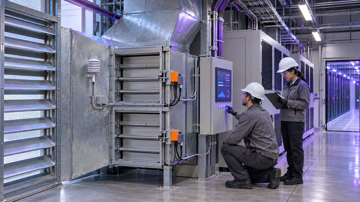
The team should verify that outdoor-air, return-air, relief-air, and exhaust paths are clear. Inspect damper blades, linkages, seals, actuator couplings, filters, screens, louvers, and access doors. Check for unusual differential pressure across filters and coils. If the design uses an air-to-air heat exchanger, confirm that bypass dampers and wheel or plate sections respond as intended.
Use a witnessed stroke test where practical. Command the damper to a known position, confirm the physical position or proof signal, and record the response time. A position feedback value that never changes is not acceptable evidence of movement. Note any actuator that hunts, stalls, moves slowly, or requires an unexplained override.
4. Review filtration and outdoor-air quality controls
The filtration strategy should be explicit. Record the filter type, installation date, differential-pressure limit, spare availability, and who is authorized to change it. Confirm that the intake location and screens are appropriate for the site’s surrounding environment. Facilities teams near traffic, industry, salt air, wildfire smoke, or construction may need additional monitoring or a more conservative lockout strategy.
For a direct economizer, check that the operating procedure explains what happens when outdoor-air quality deteriorates. For an indirect design, verify that the heat exchanger and seals maintain the intended separation between outdoor air and data-hall air. Include a clear trigger for disabling economizer operation and returning to the approved mechanical mode.
5. Prove the transition with a low-risk test
Schedule the first seasonal changeover during a staffed maintenance window or other approved operating period. Identify the responsible operator, the controls specialist, the mechanical technician, and the escalation contact. Agree in advance on the stop criteria.
During the test, record:
- Initial operating mode, outdoor conditions, room conditions, active alarms, fan speeds, and mechanical cooling status.
- The command or condition that enables the economizer.
- Damper positions, actuator proof, mixed-air temperature, supply-air temperature, and fan response.
- Rack-inlet temperature distribution and any localized hot spots.
- Humidity or dewpoint movement, not just dry-bulb temperature.
- Chiller, DX, or reheat response as mechanical cooling stages down or remains available.
- Alarm delivery, acknowledgment, and escalation behavior.
- The time and conditions required to return to mechanical cooling.
Stop the test if rack-inlet conditions trend outside the approved envelope, if a required sensor becomes unreliable, if pressure control destabilizes, if a damper fails to prove, or if the fallback system cannot be demonstrated. The purpose of the test is to prove readiness, not to maximize economizer hours on the first attempt.
6. Verify the fallback path
The fallback review should be a separate checklist, not an assumption. Confirm that chillers, DX units, CRAH coils, control valves, pumps, condenser systems, and associated electrical feeders are available in the intended standby arrangement. Check that an economizer lockout does not leave a valve closed, a compressor disabled, or a lead-lag sequence in an unexpected state.
The operator should be able to answer three questions quickly:
- What condition will force the site back to mechanical cooling?
- Which control point or procedure performs that change?
- How will the team know the fallback succeeded?
If the answers depend on one person remembering an undocumented workaround, the system is not ready for routine seasonal operation.
7. Make the change visible to the whole shift team
Update the shift log, operating procedure, alarm response guide, and maintenance calendar. Explain the mode change at the handoff. Include the expected trend shape, the active lockouts, the location of the equipment, and the person who can authorize a return to mechanical cooling.
For a colocation site, coordinate customer communications according to the approved change process. The message should describe the operational window and monitoring plan without implying that the customer must diagnose facility controls.
Which Training Fits This Situation
The most relevant foundation is Cooling Systems Design & Optimization, an 8-hour comprehensive course in the Cooling & Efficiency track. It gives engineers and facility managers a broader view of cooling-system design, efficiency decisions, and the operating tradeoffs behind economization. It is a useful fit when the person approving the changeover needs to understand why the sequence uses outdoor-air conditions, airflow control, and mechanical backup together.
For technicians who need a more focused path, HVAC Systems Troubleshooting Essentials and Mechanical Systems & Equipment Maintenance address the equipment-side work: sensors, fans, coils, dampers, actuators, and maintenance conditions that determine whether the sequence can be trusted. Energy Efficiency & PUE Optimization can help managers connect cooling-mode decisions to facility energy performance without reducing the decision to a single PUE number.
The Cooling & Facilities Efficiency Bundle groups six real courses for HVAC and facilities technicians, including Cooling Systems Design & Optimization, HVAC Systems Troubleshooting Essentials, Energy Efficiency & PUE Optimization, Mechanical Systems & Equipment Maintenance, Data Center Cooling System and Refrigerant Safety Training, and Building Envelope Fundamentals. A bundle can make sense for a team that owns cooling across design review, troubleshooting, maintenance, and efficiency. An individual course may be a better fit when a new operator only needs a defined foundation before working under site procedures.
Training should be assigned by role and task. A controls engineer may need the design and BAS context, while a mechanical technician may need troubleshooting and equipment maintenance. The shift operator needs to recognize the active mode, interpret alarms, and execute the approved fallback procedure. None of these courses replaces site-specific qualification, supervised hands-on work, manufacturer instructions, or the facility’s authorized operating procedures. Learners receive a certificate of completion for the course, which supports a training program but is not a regulatory license or certification.
Common Mistakes to Avoid
- Enabling economizer operation because the outdoor temperature is low while ignoring dewpoint, humidity, air quality, or rack-inlet conditions.
- Treating a BAS command as proof that a damper, actuator, valve, or fan actually moved.
- Testing only at the central plant and failing to review the cold aisle, return path, and localized rack temperatures.
- Leaving a maintenance override active after troubleshooting and then blaming the sequence when seasonal conditions change.
- Skipping filter differential-pressure checks because the filters “look clean” from the access side.
- Changing the operating mode without recording the baseline, so the team cannot tell whether temperatures or fan energy improved.
- Designing a return-to-mechanical procedure that depends on one controls specialist being on call.
- Calling the changeover a commissioning activity once and never rehearsing it again after software, sensor, damper, or equipment changes.
- Buying broad training without assigning a role, a required outcome, and a site-specific supervised practice step.
Key Takeaway
An airside economizer changeover is a coordinated facilities operation, not a seasonal toggle. The site should prove the mode, sensors, dampers, filtration, humidity controls, alarms, and mechanical fallback as one operating chain before using the sequence routinely. The best efficiency result is the one that preserves stable rack-inlet conditions and gives every shift a clear recovery path.
This week, walk one economizer air path with a mechanical technician and controls specialist, record the current lockout and fallback conditions, and schedule a witnessed changeover review before the next favorable weather window.
Sources
- U.S. Department of Energy, Best Practices Guide for Energy-Efficient Data Center Design
- ASHRAE Handbook, Data Centers and Telecommunication Facilities
- U.S. Department of Energy, Cooling Water Efficiency Opportunities for Federal Data Centers
- U.S. Environmental Protection Agency, Facilities Manual Volume 2 Architecture and Engineering Guidelines