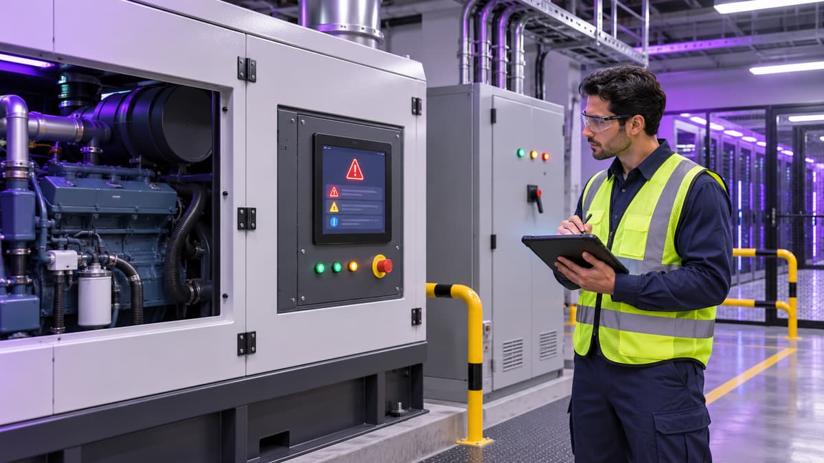
The Operational Question
When a standby generator control panel shows an alarm, the first decision is not whether to silence the horn. It is whether the alarm represents an active threat to starting, transferring, cooling support, fuel delivery, exhaust, or safe maintenance. A technician who treats every alarm as a nuisance can hide a developing failure, while a technician who treats every message as an emergency can create unnecessary switching, dispatch, and escalation activity during a critical operating condition.
This guide explains how data center technicians and supervisors can triage generator control panel alarms without guessing at the cause or bypassing site procedures. It separates immediate life-safety and availability concerns from alarms that can be investigated under an approved work plan. The reader will learn what information to capture, which equipment relationships to check, when to stop local troubleshooting, and how to turn one alarm event into a useful training and preventive-maintenance improvement.
The focus is the physical standby-power system: engine, generator, starting batteries, jacket-water heater, fuel system, breaker, automatic transfer switch, annunciator, ventilation, exhaust, and the controls that connect those pieces. This is not a substitute for the manufacturer manual, the site's emergency operating procedure, or qualified electrical and mechanical supervision. It is a readiness framework for the minutes between seeing an alarm and deciding what happens next.
Who This Affects
This issue affects the people who receive, acknowledge, investigate, or make decisions from generator alarms:
- Critical facilities technicians watching a local generator display or remote annunciator.
- Electrical technicians responsible for generator breakers, automatic transfer switches, and emergency distribution.
- Mechanical technicians supporting engines, cooling loops, fuel systems, exhaust, and ventilation.
- Facility managers who coordinate maintenance windows, vendor response, and risk acceptance.
- NOC staff who may receive a generator alarm before a facilities technician is at the equipment.
- EHS or safety leads who review isolation, lockout/tagout, hot surfaces, fuel hazards, and emergency access.
- Commissioning teams and contractors validating alarm points before a new hall or plant enters operations.
The same triage problem appears in enterprise sites, colocation facilities, hyperscale campuses, and edge locations, but the consequences differ. A campus with multiple generator sets may have time to compare alarms across a paralleling lineup. A small edge site may have one generator, a short battery ride-through period, and no technician on site. A colocation site may need to coordinate with a customer-facing incident process while protecting the privacy of tenant information.
The situation can begin with a local “not in auto” message, a low-coolant warning, a charger failure, an engine shutdown, a breaker status mismatch, or a communication-loss alarm. It can also appear as a remote point that lacks enough context to distinguish a genuine equipment condition from a failed sensor or stale communication path.
What Can Go Wrong
Generator alarms are often connected. A low-voltage starting-battery alarm can become a failure to crank. A failed jacket-water heater can create a cold-start problem that does not appear until a transfer is requested. A cooling alarm can force an engine shutdown during a prolonged outage. A breaker or automatic transfer switch status mismatch can make the control room believe that emergency power is available when the load is not actually supported.
The most serious risks include:
- Loss of starting capability. Weak batteries, a failed charger, loose connections, or an isolated starting circuit can prevent the engine from cranking when utility power is lost.
- Unexpected engine shutdown. Low oil pressure, high coolant temperature, overspeed, fuel problems, or protective trips can remove a source that the electrical design depends on.
- Unsafe exposure. Fuel leaks, hot exhaust surfaces, rotating parts, battery electrolyte, and arc-flash hazards create risks that cannot be solved by pressing reset.
- Incorrect switching decisions. A technician may move a breaker, transfer switch, or operating mode selector based on an incomplete picture of the system state.
- False confidence from a cleared alarm. A message can disappear when a sensor recovers, a communication path restarts, or a condition temporarily changes. Clearing the display does not prove the underlying problem is gone.
- Poor incident evidence. If nobody records the first alarm, time, operating mode, load, and related equipment states, the team may be unable to distinguish a control fault from a real equipment event.
Standards and regulations provide useful context, but they do not replace the facility's engineered sequence or the equipment manufacturer's instructions. OSHA requirements for control of hazardous energy and electrical safe work practices are relevant when technicians isolate or work on equipment. NFPA 110 provides a framework for emergency and standby power systems, but the site's actual alarm priorities, testing intervals, and switching steps must be verified against the installed system and approved procedures.
An alarm that appears minor can also create a compliance and cost problem. Repeated charger-failure alarms may show that batteries are being replaced without correcting the charging environment. Repeated communication alarms may show that a monitoring point has no owner. Repeated “not in auto” conditions may show a work-control weakness rather than a generator defect.
What Managers Should Check
A manager should make sure the team has a consistent triage sequence that protects people first, preserves the generator's availability, and produces usable evidence. The following framework can be adapted to the site's emergency operating procedure.
1. Confirm the alarm and the operating context
Before interpreting the message, record the exact text, point name, priority, time, and source. Note whether the generator is stopped, running unloaded, carrying load, in a test mode, in manual, in automatic, or unavailable for maintenance. Compare the local panel with the remote annunciator or BMS only after confirming that the two systems use the same point definition.
Record the related electrical state:
- Utility source condition and whether an automatic transfer switch has initiated a sequence.
- Generator output voltage, frequency, current, and breaker position if the procedure allows viewing those values.
- Whether the emergency bus is energized and which loads are being supported.
- Whether another generator, UPS, or alternate source is available.
- Whether a maintenance bypass, temporary generator, or planned outage is already in progress.
This first record prevents a common mistake: investigating the alarm as a standalone message after the system has already moved into a different operating state.
2. Screen for immediate hazards
The technician should stop and escalate immediately when the alarm may involve a life-safety or equipment-protection condition. Examples include visible fuel or coolant leakage, smoke, fire, abnormal exhaust, unusual vibration, suspected overspeed, exposed energized parts, battery damage, or a strong odor that suggests an overheating electrical component.
The site procedure should identify who has authority to call emergency services, shut down equipment, restrict access, or declare a generator unavailable. A person who is not qualified for the task should not open electrical enclosures, defeat an interlock, bypass a protective trip, or enter a restricted area merely to obtain more information.
3. Classify the alarm by function
A practical classification helps the technician choose the next safe question:
- Start and readiness: low battery voltage, charger failure, engine not in auto, start-failure history, or emergency-stop status.
- Engine protection: low oil pressure, high coolant temperature, overspeed, failed sensor, or shutdown lockout.
- Fuel and combustion: low day-tank level, pump fault, fuel pressure, leak detection, clogged filter indication, or exhaust restriction.
- Cooling and ventilation: jacket-water heater, radiator fan, room temperature, airflow, louver, or ventilation-fan status.
- Electrical output: generator voltage, frequency, breaker trip, excitation, phase relationship, or output protection.
- Transfer and distribution: automatic transfer switch source availability, transfer position, bypass/isolation status, or emergency-bus mismatch.
- Controls and communications: panel power, network path, remote annunciator, BMS gateway, time synchronization, or stale data.
The classification is not a diagnosis. It is a way to avoid jumping from a message such as “engine fault” directly to a part replacement.
4. Compare local indications with independent evidence
For a communications alarm, check whether the local panel still shows current values and whether the remote system's last-update time is changing. For a sensor alarm, compare the reading with a safe independent indication, such as an approved gauge, a second sensor, or a trend from a known-good point. Do not defeat a sensor or force a value simply to clear an alarm.
For an electrical alarm, verify the control-panel indication against the approved one-line, breaker status, transfer-switch indication, and control-room state. Status points can be wired incorrectly, inverted, delayed, or unavailable while a control power supply is down. A green icon is not proof that the generator is ready to accept load.
5. Check recent work and changes
Ask what changed before the alarm appeared. Review the work order, test script, maintenance log, fuel delivery record, battery service record, and controls change history. Recent causes may include:
- A technician left the generator in manual or test mode.
- A breaker or disconnect remained open after maintenance.
- A battery charger was isolated or returned with an incorrect setting.
- A sensor was replaced but not calibrated or mapped to the right point.
- A BMS or annunciator point was renamed, suppressed, or reconfigured.
- A fuel or cooling component was serviced without completing the restart checklist.
This check is especially important after commissioning and vendor work. The right question is not “Who touched it?” but “Which approved change, test, or isolation could explain the current state?”
6. Define the stop point and escalation path
Every alarm response should identify what the on-site technician may observe, what requires a qualified specialist, and what requires a manager or incident commander. Escalation thresholds should include both equipment conditions and time conditions. A generator that remains unavailable while the UPS ride-through window is shrinking deserves escalation even if the panel alarm has not changed.
The handoff should include the exact alarm, equipment identity, operating mode, load state, related alarms, actions already taken, hazards observed, and the next decision required. “Generator alarm, vendor called” is not enough information for the incoming shift.
7. Close the loop after stabilization
When the condition is controlled, preserve the original alarm history if the system permits. Capture screenshots or trend exports according to site policy, attach the event to the work order, and record whether the alarm was confirmed, cleared, inhibited, or still unresolved. A reset is an action, not a root-cause finding.
Managers should trend recurring alarms by generator, site, vendor, component, and operating mode. The objective is to find weak signals before they combine during an outage or test.
Which Training Fits This Situation
This topic sits in the Power & Electrical track because generator alarm triage crosses engine readiness, electrical output, transfer logic, and safe work control. A technician who only understands the engine may miss a breaker or transfer condition. A technician who only understands the electrical one-line may miss a cooling or fuel condition that will stop the engine.
The most direct individual course is Generator Operations & Maintenance, which can support a technician's understanding of generator components, routine checks, maintenance coordination, and the difference between a normal test condition and an abnormal operating state. Emergency/Standby Power Systems Fundamentals is useful for technicians, supervisors, and NOC partners who need to understand how generators, transfer equipment, emergency distribution, and ride-through systems work together.
For the safety layer, Electrical Safety & Best Practices helps frame the boundaries around inspection, switching, isolation, and escalation. A team that works around starting batteries should also consider Data Center UPS and Battery System Safety Training when battery rooms and UPS plants are part of the same response path.
For a role-based plan, a facility manager might assign:
- Generator Operations & Maintenance to mechanical and electrical technicians who inspect or service the sets.
- Emergency/Standby Power Systems Fundamentals to operations supervisors and NOC staff who interpret source availability.
- Electrical Safety & Best Practices to anyone who may operate, isolate, or coordinate work around emergency distribution.
- Data Center Operations Management to leads who own procedures, logs, handoffs, and readiness reviews.
The Power & Electrical Systems Bundle is a practical fit when a team needs coordinated coverage across power architecture, UPS, generators, batteries, EPO procedures, electrical safety, and emergency power. These are self-paced knowledge courses that support a site's training program. They are not certification exams and do not replace site qualification, manufacturer instruction, or authorization to perform a switching or maintenance task. Learners receive a certificate of completion after finishing the course, but the employer still determines whether a person is qualified for a specific duty.
Common Mistakes to Avoid
- Silencing the alarm before recording the exact message and time.
- Treating “not in auto” as a harmless status when the generator is part of the active contingency plan.
- Resetting a protective trip without confirming why it occurred and whether the procedure permits a reset.
- Assuming a BMS point is current because the graphic looks normal.
- Opening an enclosure or touching a battery system to gather information that the local procedure does not authorize.
- Calling a vendor without telling the vendor the generator's mode, load state, related alarms, and recent work.
- Leaving a temporary alarm inhibit in place after a test or repair.
- Closing the work order with “tested OK” when the original alarm was not reproduced or explained.
- Training mechanical and electrical teams separately without practicing the handoff between engine conditions and emergency-bus conditions.
- Using a generic alarm list that does not match the installed generator model, paralleling controls, transfer switches, and site sequence.
A mature response process makes it easy to do the safe thing. It shows the technician where to stand, what to observe, what not to touch, who decides, and what evidence to preserve. It also gives managers a way to distinguish a one-time sensor fault from a recurring readiness problem.
Key Takeaway
Generator control-panel alarms are decision points, not just messages to clear. The strongest response connects the alarm to the generator's operating mode, the emergency distribution state, recent work, immediate hazards, and the team's authority to act. This week, walk one generator with a technician and verify that the local alarm list, remote points, escalation contacts, and stop points match the current equipment and procedure.
Sources
- Occupational Safety and Health Administration: The control of hazardous energy (lockout/tagout), 29 CFR 1910.147
- Occupational Safety and Health Administration: Electrical safety-related work practices, 29 CFR 1910.333
- NFPA: NFPA 110, Standard for Emergency and Standby Power Systems
- U.S. Department of Energy: Operations and Maintenance Best Practices Guide
- HAZWOPER OSHA Training, LLC: Data Center Training Course Catalog